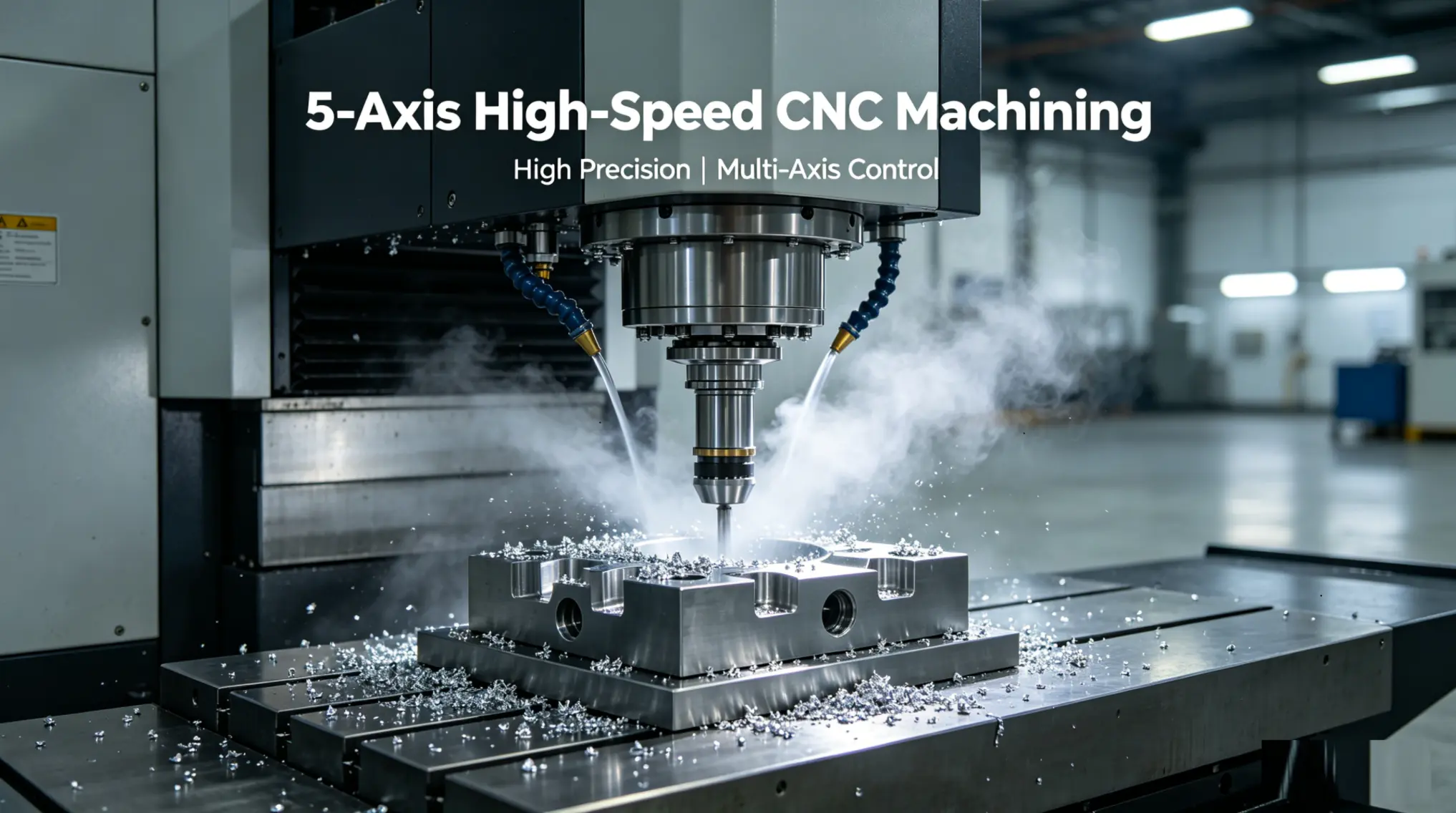
5-Axis High-Speed CNC Machining: How Speed and Multi-Axis Motion Work Together
5-axis high-speed CNC machining combines simultaneous multi-axis tool movement with spindle speeds of 15,000-42,000 RPM, light radial engagement (5-15% of cutter diameter), and high feed rates (200-800 in./min) to remove material 2-4x faster than conventional 5-axis approaches. The result: shorter cycle times, better surface finishes (Ra 0.2-0.8 µm without secondary polishing), and longer tool life on difficult materials like titanium and Inconel. It's the standard approach for aerospace structural parts, turbine blades, and medical implants where geometry is complex and cycle time is money.
Standard 5-axis CNC machining already cuts setup time by 60-80% compared to 3-axis work. Adding high-speed machining (HSM) strategies on top of that changes the economics of complex part production entirely. Instead of heavy, slow cuts with large tools, 5-axis high-speed CNC machining uses lighter cuts at much higher feed rates, keeping the tool in constant motion and the chip load thin but consistent.
The combination matters because 5-axis tool orientation and high-speed feed rates solve different problems that compound each other. The 5-axis motion keeps the tool at the optimal cutting angle on sculpted surfaces (no sudden direction changes, no tool rubbing). The high-speed strategy keeps chip thickness in the sweet spot where heat goes into the chip, not the workpiece. Together, they produce parts with surface finishes that often eliminate secondary polishing, in cycle times that make complex geometry economically viable at lower volumes.
This guide covers how 5-axis HSM actually works at the spindle and toolpath level, what makes it different from conventional 5-axis, which materials and parts benefit most, and the practical numbers (RPM, feed rates, step-over, engagement) that determine whether you get the efficiency gains or just burn through cutters.
What Is 5-Axis High-Speed CNC Machining?
5-axis high-speed CNC machining is a strategy that combines simultaneous 5-axis tool movement with high-speed machining principles: high spindle RPM (15,000-42,000 RPM), high feed rates (200-800 in./min depending on material), light radial depth of cut (typically 5-15% of cutter diameter), and continuous, smooth toolpaths that avoid sudden direction changes.
The "high-speed" label doesn't just mean spinning the spindle faster. It's a complete approach to material removal that prioritizes consistent chip load and constant tool engagement over heavy depth of cut. In conventional machining, you take deep cuts at moderate feed rates. The tool spends significant time buried in material, generating heat that transfers into the workpiece. In HSM, the tool skims material in thin layers at high velocity. Each chip is small, carries heat away efficiently, and the tool moves to the next cut before thermal buildup occurs.
When you apply this on a 5-axis platform, the rotational axes keep the tool perpendicular (or at the programmed lead/tilt angle) to the surface being cut. On a compound curve like a turbine blade, a 3-axis HSM approach forces the ball-nose cutter into varying engagement angles as the surface curves away from vertical. The cutting conditions change constantly, producing inconsistent chip load and visible witness lines on the surface. On a 5-axis HSM setup, the A and B axes continuously reorient the tool to maintain the optimal engagement angle. Chip load stays consistent. Surface finish stays uniform.
How Does High-Speed 5-Axis Differ from Conventional 5-Axis?
The machine hardware is often identical. The difference is in the cutting strategy, toolpath generation, and spindle utilization. Here's a direct comparison:
Parameter
Conventional 5-Axis
High-Speed 5-Axis
Spindle RPM
6,000-15,000
15,000-42,000
Feed rate
40-150 in./min
200-800 in./min
Radial depth of cut (Ae)
30-60% of cutter diameter
5-15% of cutter diameter
Axial depth of cut (Ap)
0.5-2x cutter diameter
1-3x cutter diameter (full flute engagement)
Chip thickness
0.003-0.008 in.
0.001-0.003 in.
Heat distribution
Mostly into workpiece
Mostly into chip (carried away)
Material removal rate
Moderate
2-4x higher (thin but fast cuts)
Surface finish achievable
Ra 0.8-3.2 µm
Ra 0.2-0.8 µm
Tool life
Moderate (heat degrades edge)
30-60% longer (less thermal load per tooth)
Toolpath type
Standard contour, pocket, profile
Trochoidal, adaptive, constant-engagement
Machine requirement
Standard 5-axis
5-axis with high-speed spindle, look-ahead control, rigid linear guides
The key insight: high-speed 5-axis doesn't cut less material per minute. It cuts more, by making thousands of light, fast passes instead of hundreds of heavy, slow ones. The metal removal rate (cubic inches per minute) is often 2-4x higher because the tool is always in motion, always cutting, never dwelling.
What Are the Critical Parameters for 5-Axis HSM?
Getting the parameters wrong on high-speed 5-axis work doesn't just reduce efficiency. It snaps tools, damages workpieces, and can crash the machine. Here are the numbers that matter.
Spindle speed (RPM): Calculated from surface speed (SFM) and cutter diameter. For a 0.500 in. ball-nose end mill in 6061-T6 aluminum at 1,200 SFM: RPM = (1,200 x 3.82) / 0.500 = 9,168 RPM. For titanium Ti-6Al-4V at 180 SFM with the same cutter: RPM = (180 x 3.82) / 0.500 = 1,375 RPM. The material dictates the surface speed; the cutter diameter dictates the RPM. Smaller cutters need higher RPM to maintain the same surface speed.
Feed rate (in./min): Feed rate = RPM x number of flutes x chip load per tooth. For a 4-flute, 0.375 in. end mill at 20,000 RPM with 0.002 in./tooth chip load: feed = 20,000 x 4 x 0.002 = 160 in./min. On aluminum with 0.004 in./tooth: feed = 20,000 x 4 x 0.004 = 320 in./min. These numbers are real, and the machine needs look-ahead control (typically 100-200 blocks) to process the toolpath data fast enough to maintain these feed rates through tight curves.
Radial engagement (Ae): This is where HSM diverges most from conventional cutting. Instead of burying the cutter 50% into the material, HSM uses 5-15% radial engagement. For a 0.500 in. cutter, that's 0.025-0.075 in. of radial contact. The trade-off: you need more passes to clear the same pocket, but each pass is dramatically faster and generates far less heat. The net result is faster total cycle time with better surface quality.
Chip thinning effect: At low radial engagement, the actual chip thickness is much less than the programmed feed per tooth. A 0.500 in. cutter at 10% Ae with 0.002 in./tooth feed actually produces chips only 0.0009 in. thick. To maintain effective cutting (and avoid rubbing, which kills tools), the programmed feed must be increased to compensate. Most CAM systems calculate this automatically when using adaptive or trochoidal toolpaths, but verify it manually on critical setups.
Look-ahead and block processing speed: At 400 in./min feed rate with toolpath segments every 0.010 in., the controller processes 40,000 blocks per minute (667 blocks per second). If the controller can only handle 200 blocks per second, it starves the axes, causing micro-hesitations that leave witness marks on the surface. Modern high-speed controls process 1,000-2,000 blocks per second. This is a machine specification, not a programming parameter, so verify it when selecting equipment.
Which Materials Benefit Most from 5-Axis HSM?
High-speed 5-axis machining isn't equally beneficial on all materials. The advantage is largest on materials where conventional cutting generates problematic heat or where surface finish quality eliminates secondary operations.
Aluminum alloys (6061-T6, 7075-T6): maximum benefit
Aluminum is where HSM delivers the most dramatic cycle time reductions. Spindle speeds reach 30,000-42,000 RPM on dedicated HSM machines, with feed rates above 600 in./min. A large aerospace structural part (wing rib, bulkhead) that takes 6 hours on conventional 5-axis can drop to 2-3 hours with HSM toolpaths. Surface finishes of Ra 0.4-0.8 µm are achievable directly off the cutter, eliminating hand polishing.
The risk: at these speeds, chip evacuation becomes critical. If chips re-cut, they weld to the surface (built-up edge), ruining the finish. High-pressure coolant (500-1,000 psi) or air blast directed at the cutting zone keeps chips clear.
Titanium alloys (Ti-6Al-4V): significant benefit
Titanium's low thermal conductivity means heat concentrates at the cutting edge. Conventional heavy cuts overheat the tool rapidly (tool life under 15 minutes at aggressive parameters). HSM's light engagement distributes heat into the chip stream instead, extending tool life to 25-40 minutes per edge. Spindle speeds are lower (1,500-4,000 RPM for titanium) but feed rates are still 2-3x conventional because chip load compensation allows faster programmed feed at low Ae.
The 5-axis component adds another layer: on contoured titanium aerospace parts (blisks, structural fittings), maintaining the correct lead angle (typically 10-15 degrees of tilt away from vertical) prevents the center of a ball-nose cutter from rubbing. Center rubbing at the tool tip generates zero chip thickness and 100% heat, which is exactly the condition that causes titanium to work-harden and destroy tools.
Nickel alloys are extremely heat-resistant (that's the point of using them in turbine engines), which means the heat generated during cutting doesn't go into the chip easily. HSM helps by reducing the time each tooth spends in the cut, but the overall spindle speeds are still limited to 300-800 SFM. The 5-axis advantage is more important than the speed advantage here: maintaining constant tool-to-surface angle on complex turbine blade geometry prevents the variable engagement conditions that cause catastrophic tool failure on nickel alloys.
Hardened steels (50-62 HRC): moderate benefit
Hard milling with 5-axis HSM has replaced grinding for many die and mold finishing operations. Carbide ball-nose end mills at 15,000-25,000 RPM with 0.002-0.005 in. step-over produce Ra 0.2-0.4 µm directly, which is comparable to EDM + polishing at a fraction of the time. The 5-axis orientation keeps the ball-nose cutter away from its center (zero-speed zone), using the shoulder of the ball where cutting is most effective.
Plastics and composites: limited HSM benefit
Engineering plastics like PEEK, Delrin, and polycarbonate don't need high-speed spindles. They're thermally sensitive, so the speed advantage (removing heat via chips) becomes a disadvantage at extreme RPM (the chips heat the material through friction before leaving). Standard 5-axis at moderate speeds (8,000-15,000 RPM) with sharp, uncoated tools produces the best results on plastics.
What Parts Are Best Suited for 5-Axis High-Speed Machining?
The ideal part for 5-axis HSM has compound curves, multiple features on different faces, thin walls that deflect under heavy cutting forces, and a surface finish requirement that would otherwise need secondary polishing.
Part Type
Industry
Why 5-Axis HSM
Key Spec
Turbine blades and blisks
Aerospace
Freeform airfoil surfaces, titanium or Inconel, Ra < 0.8 µm finish direct from cutter
Airfoil profile ±0.001 in.
Structural wing ribs
Aerospace
Large aluminum parts with deep pockets, thin webs (0.040-0.080 in.), high material removal volume
Aluminum thin-wall housings with multiple port faces, cooling jacket pockets
Wall thickness ±0.003 in., flatness 0.001 in.
Lens molds
Optics
Freeform optical surfaces in nickel or copper, sub-micron surface finish
Profile ±0.0001 in., Ra < 0.05 µm
If your part is a simple prismatic block with features on one or two faces, 5-axis HSM is overkill. A standard 3-axis VMC at conventional speeds handles that geometry more cost-effectively. The ROI on 5-axis HSM shows up when geometry complexity and surface finish requirements make conventional approaches either impossible or prohibitively slow.
What Are the Limitations and Trade-offs?
No machining strategy is universally optimal. Here's where 5-axis HSM has real limitations.
Machine cost: A 5-axis machining center with a 20,000+ RPM spindle, high-speed control, and through-spindle coolant costs $400,000-1,500,000 depending on work envelope and configuration. Hourly rates at shops with this equipment run $150-300/hr, compared to $75-150/hr for standard 3-axis VMCs.
Programming complexity: HSM toolpaths require CAM software with adaptive milling, constant-engagement strategies, and chip thinning compensation. Programming a complex 5-axis HSM job takes 2-4x longer than programming the same part for conventional cutting. If your shop runs one-off prototypes, the programming time can exceed the machining time.
Not all 5-axis machines support HSM: A 5-axis machine with a 10,000 RPM spindle and a basic controller (200 block/sec look-ahead) cannot execute true HSM toolpaths. The spindle is too slow, and the controller starves, causing surface defects. "5-axis" and "high-speed" are independent capabilities that must both be present.
Thin-wall deflection at extreme parameters: HSM reduces cutting forces compared to conventional machining, but at very thin walls (below 0.030 in.), even light radial engagement can cause deflection. In those cases, alternating between opposite wall faces (climb one side, then the other) or using wax/adhesive backing to support the wall during cutting is necessary.
Chip evacuation on deep pockets: At 400+ in./min feed rates in aluminum, the volume of chips produced is enormous. If chips pack in a deep pocket, the cutter re-cuts them, which degrades surface finish and can break the tool. Flood coolant, through-tool air blast, or chip vacuum systems are not optional at these speeds.
How to Get 5-Axis High-Speed Parts Machined
When quoting 5-axis HSM work, the information you provide directly affects whether the shop quotes it efficiently or adds a safety margin that inflates the price.
Include the 3D model and a 2D drawing with GD&T. The 3D model defines geometry; the drawing defines which dimensions are critical. Without both, the shop has to assume everything is tight.
Specify material with full alloy and temper designation. "Aluminum" gets a question. "7075-T6 per AMS-QQ-A-250/12" gets a price. The alloy determines cutting speeds, which directly sets cycle time and cost.
Call out surface finish requirements per zone. "Ra 0.4 µm on airfoil surfaces, Ra 1.6 µm elsewhere" tells the shop exactly where to apply the expensive HSM finishing passes and where standard machining is sufficient.
State your volume and program timeline. 5 prototypes and 500 production parts per month have very different quoting strategies. The prototype price absorbs programming time across 5 parts; the production price amortizes it across 6,000 parts per year.
FlagShip's CNC machining services include 5-axis capability with tolerances to ±0.0001 in. on precision features. Upload your CAD file for DFM feedback and an instant quote. For complex geometry that benefits from HSM strategies, the engineering team can advise on the most cost-effective approach.
Frequently Asked Questions
What is 5-axis high-speed CNC machining?
It combines simultaneous 5-axis tool movement (X, Y, Z, A, B axes) with high-speed machining strategies: spindle speeds of 15,000-42,000 RPM, feed rates of 200-800 in./min, and light radial engagement (5-15% of cutter diameter). The result is 2-4x faster material removal compared to conventional 5-axis cutting, with superior surface finish (Ra 0.2-0.8 µm) and 30-60% longer tool life.
How is high-speed 5-axis different from standard 5-axis machining?
Standard 5-axis uses moderate spindle speeds (6,000-15,000 RPM) with heavy depth of cut (30-60% radial engagement). High-speed 5-axis uses faster spindles, lighter cuts, and continuous toolpath strategies like trochoidal and adaptive milling. The total material removal rate is 2-4x higher because the tool stays in constant motion with consistent chip load.
What spindle speed is needed for 5-axis high-speed machining?
Minimum 15,000 RPM for most HSM applications. Aluminum aerospace work benefits from 30,000-42,000 RPM. Titanium requires lower RPM (1,500-4,000) but still uses HSM feed rate strategies. The controller must also support 1,000+ block/second look-ahead to process the dense toolpath data at high feed rates.
Which materials benefit most from 5-axis HSM?
Aluminum alloys see the largest cycle time reduction (50-60% faster than conventional 5-axis). Titanium benefits from 30-60% longer tool life due to reduced thermal load. Hardened steels (50-62 HRC) benefit from surface finish quality that replaces EDM and polishing. Nickel alloys benefit primarily from the constant engagement angle that 5-axis provides, with moderate speed gains.
What surface finish can 5-axis high-speed machining achieve?
Ra 0.2-0.8 µm (8-32 µin.) directly off the cutter without secondary polishing. On hardened steel dies, Ra 0.2-0.4 µm is achievable with ball-nose end mills at 15,000-25,000 RPM and 0.002-0.005 in. step-over. On aluminum, Ra 0.4-0.8 µm is standard. Mirror finishes (Ra <0.1 µm) still require polishing after machining.
What does a 5-axis high-speed CNC machine cost?
Machine cost ranges from $400,000 to $1,500,000 depending on work envelope, spindle speed rating, and control system capability. Shop hourly rates for 5-axis HSM typically run $150-300/hr. The higher machine rate is offset by 2-4x faster cycle times on complex parts, so total part cost is often lower than conventional 5-axis for geometries that fully utilize HSM strategies.
When should I NOT use 5-axis high-speed machining?
Skip 5-axis HSM for simple prismatic parts (flat pockets, straight walls) that run efficiently on 3-axis at conventional speeds. Also skip it for very small production runs (1-3 parts) where programming time exceeds the cycle time savings. For thermally sensitive plastics (PEEK, Delrin, polycarbonate), standard speeds with sharp tools produce better results than high-speed approaches.
What is chip thinning and why does it matter for HSM?
At low radial engagement (5-15% Ae), the actual chip thickness is much less than the programmed feed per tooth. A 0.500 in. cutter at 10% Ae with 0.002 in./tooth feed produces chips only 0.0009 in. thick. If the CAM software doesn't compensate by increasing the programmed feed, the tool rubs instead of cutting, generating heat and destroying the edge. Most modern CAM systems handle this automatically in adaptive toolpath modes.
 Tony Chow
Published Date: 2026/4/24
Tony Chow
Published Date: 2026/4/24